Troglodyte: Driverless vehicles 4


The idea is perhaps geared a bit too much around the concept of a “driver” and the thinking that she is actively following what the car does.

The purpose of Project Troglodyte is to hunt for bad patents and to show what went wrong. For more information, see the  web page.


Zone Driving

This analysis is part of a series of Google driverless car related patents and applications. This application can be found here.

When reading the analysis it might be interesting to keep in mind that Google possibly uses this idea in their test cars all the time. It would be interesting to know how much the test drives are affected by it. If driverless car development wasn’t a sideshow for Google this could even have an impact on its market value as it could conceal the technology readiness level.

Figure 1.

TIER 1: SUMMARY

This application describes a way of generating, sharing and using information about areas where the driver might want to take control of an autonomous vehicle. These areas are called zones in the text. The idea is perhaps geared a bit too much around the concept of a “driver” and the thinking that they are actively following what the car does. I for one think the exact opposite is the reason to buy an autonomous vehicle in the first place.

My real problem with this idea is the wordplay; a zone is defined as a place where the autonomous vehicle is not that autonomous or where there is a risk that it can’t cope with the environment. If a company wants to come to market before it can handle every aspect of the traffic environment it need this sort of approach. For example the vehicle avoids certain types of intersections or areas of intense pedestrian traffic where it might not be able to move as the pedestrians would be very close. One might be able to argue that a system driving solely on highways needing the driver to take control when exiting the highway is using this system if it automatically recognizes the upcoming exit and gives a warning. This in turn is pretty much a must, as highways sometimes morph to regular roads. Defining the points where control is needed as zones makes it sound like this would be something completely new.

While I don’t know how novel this idea is (I didn’t do a prior art search) it is certainly a powerful way of categorising this information. After realising what is meant by a zone the rest of the related ideas kind of flow naturally.

I would imagine that this is something the development team stumbled into as they wanted to try the car before the algorithms were able to control it in all circumstances. The difficulty of environments likely varies greatly, so it is prudent to start with the easier ones to get some experience. Come to think of it, it is possible that the first autonomous cars will be limited in their ability to navigate completely independently as they probably will be developed from cars that have some of the required features but not all, for example from cars that will be able to drive in light traffic on divided highways.

One important aspect might also be the reluctance of drivers to leave all control to the computer, this fear would likely be alleviated if there was a possibility to set parameters that trigger a notification about difficult spots. As one of the main reasons to get an autonomous car is to be able to do something else when travelling, this sort of warning/notification feature might be a must for all early models.

I noted in some of the other driverless car analysis that they are transition period ideas, that is also true in this case. The proposed feature would get most use when the roads are not built for autonomous vehicles and people are not used to the new technology. After the transition period it might get very little use as it would be required only in exceptional circumstances.


TIER 2: AVOIDING LICENSING

The zone concept could be further developed by adding some parameters such as time of day, day of week, temperature, forecasted low friction, local rush hour etc. Pop-up zones could be created if a school bus is detected or a driver indicates that one is close by, this sort of zone could expire for example in 15 minutes. The computer could automatically generate zones if it needs to use unexpected deceleration or manoeuvre violently to avoid impact.

Further there could be a voting scheme to establish and remove a zone. For example if one driver indicates a zone is needed those approaching immediately behind would get a zone warning, but if none of them takes control of their autonomous vehicle the zone would not be established.

Two obvious methods of bypassing exist, the driver follows the situation closely or the car really is autonomous. Neither is good for the business of selling autonomous cars. One possibility might be to analyze map data constantly to identify spots where the computer might need help. Roadworks are often indicated by signs which can be recognized by cameras. Some places could be indicated by a special sign which might have an RF transmitter to make them detectable beyond visible range and add some determinism. These however do not quite reach the dynamic nature of the zone idea (its best contribution I think) which could prove to be quite difficult to bypass if this application is granted in its present form.


TIER 3: TECHNICAL ANALYSIS

The word vehicle is used throughout the text, by definition it includes things such as aircraft and helicopters. Autopilots have been in use in those for some time, devices such as autothrottle seem similar to the description of taking over part of the control from the computer. Aircraft autopilots also disengage if they lose control and naturally give a warning. Almost certainly modern autopilots can be engaged for a part of the planned route and be configured to give a warning before that part ends. For example an autopilot would be used through cruise and a warning would be given when the planned descent point is reached. If the descent point is called a zone, it is at a waypoint and the waypoint information can be found on a map which is downloaded from a server the similarities a quite noticeable.

Without the zone system drivers of early autonomous vehicles may feel the need to continuously monitor the performance of the car. With it they may first set a very strict warning level and include a lot of zones and after they feel more comfortable they can let the car do more and more of the driving by itself. Because the zones are proposed to be in a map, any route can be designed so that the number of zones on the route are as few as practicable. If the driver feels tired she can select a route that is a bit longer but has less zones in it and use the time to rest.

In the description it is noted that it is not sufficient for the vehicle to be close to the zone to trigger action, the vehicle also needs to be affected the by the zone in the future. For example if the vehicle is driving on a lane that is on top of the zone on a bridge, no action is required. This is important for the functioning of the zone concept as false positives could degrade user confidence in the system. To be able to solve this problem one needs understanding of the map side of the equation: when the route is planned and then followed, the computer knows which lane it is likely going to be on when the vehicle is close to the zone. The description of this is rather sketchy and actually making a system that does this requires some knowledge of an art that is not that closely related to the zone concept.

The claims are related to the description. As mentioned above some part of the idea may have novelty issues and this of course reflects on the claims that cover that part of the description.
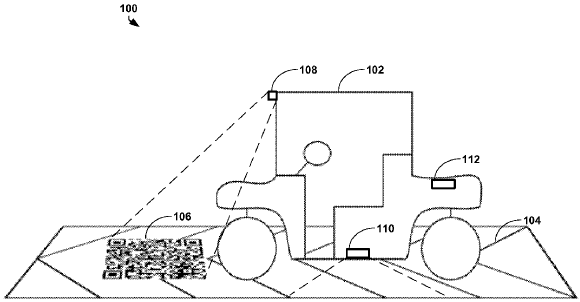
Troglodyte: Cleantech 2

“As inventors ourselves, we think this was already trivial somewhere around the year 1900 (the invention of radio).”

The purpose of Project Troglodyte is to hunt for bad patents and to show what went wrong. For more information, please see the web page.

SYSTEMS AND METHODS FOR REMOTE IRRIGATION CONTROL

[Writers: Jakke Mäkelä and Niko Porjo]

On June 5, 2012, a patent was granted (US8193930) named  “Systems and methods for remote irrigation control”.  The patent holder can now claim to own the following invention: someone has a rain sensor standing in a field; that rain sensor sends rain data to someone over a wireless network; and that information is used to control water sprinklers.

If we were to summarize our understanding of the patent, we would say it consists of saying in a complex way: “Remove the wire and insert equipment to make a wireless connection”. As inventors ourselves, we think this was already trivial somewhere around the year 1900 (the invention of radio). In the Appendix, we try to show this in much more detail.

We take a clinically analytical perspective here. We might not personally like this patent, and we see potential risks in it, but it is entirely up to the patent owner what happens with it. As we pointed out in The Trolling Triad, not everything is a patent troll that is called a patent troll.

Disclaimer: we are NOT talking about legal issues. In the patent world, it is the claims that are argued about in court. We are interested in the technical descriptions, that is, the new information that society gained by granting the patent. After all, that is the whole tradeoff behind the patent system; in exchange for a temporary monopoly to the patent holder, society gets full disclosure of what was invented.

We see nothing new here, hence no benefit to society.

The main risk we see with this patent is the precedent. In the wrong hands, this patent is broad enough to cause problems to anyone dependent on irrigation.  The main group at risk are small US companies who design or manufacture systems for irrigation control. A Google search with “irrigation control company” quickly brings up such a list.

This patent is spurious enough that it really is difficult to work around.  There are two ways to achieve such a blanket: by being very good, or by being very vague.  The patent certainly does not fall into the category of “very good”.

The deadening effect of spurious patents on the software industry is well known (see EFF). If such practices start to flow into industries that deal with crucial services, such as irrigation or food production, it is a bad precedent.  Innovation in this area will slow, and prices will rise due to the additional licensing costs. This can have a high societal impact in the long run.


TECHNICAL APPENDIX: IN-DEPTH ANALYSIS OF THE DESCRIPTION

The patent description is written around the figures and the dissection below follows this partition and may thus handle several paragraphs in one go. There is a short plain text summary of the patent text related to each figure, given in italics and followed by our comment. Each figure and its description will be analyzed and it will be shown that the description of the invention offers nothing new, in fact in terms of technology most of the content is positively ancient. It should be noted that many of the examples given as prior art fit more than one part of the description.
The technical field is described as follows “…remotely operated systems, and more particularly to a computerized system for monitoring, reporting on, and controlling remote systems by transferring information signals through a wide area network (WAN) and using software applications hosted on a connected server to appropriately process the information.”
Fig 1. Describes shortcomings of prior systems, the main message is that  wires are required to connect sensor actuators to controllers and further to more remote computers or humans running decision making algorithms and finally to power sources. —–   For example this Skylab Saturn IB Flight Manual describes how a range safety officer could use a wireless connection to trigger destruction of the vehicle based on part on telemetry readings received from the vehicle. Tracking stations forming a wireless network around the world were used to send and receive telemetry data.  —–  Radioisotope thermoelectric generators have been used to power both lighthouses and monitoring equipment on earth. In a less extreme example mobile phones have always been battery powered and since they include a microphone (sensor) and an actuator  (vibrating alert) they can be called a sensor actuator. Thus the problem of wired connections for data and power for remote units has been solved a long time ago by using wireless radio technologies.
Fig 2. According to the text fairly complex network can be constructed with wireless transceivers connecting the sensor actuators through local controllers to a network. Specific software can be run on different nodes, connections can be one way, wireless communications can be established through several nodes if they are in range and data can be gathered by and commands can be sent from computers on the network.  —–  Two abbreviations: GSM and SMS. A GSM network consists of back end infrastructure (computers, wires…) connected to base stations through either wired or in some cases wireless two way data network. Mobile devices are connected to the base stations by a radio frequency link. While in a digital system all information is transferred as digital data, the Short Message System offers an example where the originating data is something else than audio.   —–    Handheld radio transceivers or walkie-talkies have been around since at least WWII, the technical task of integrating one of these with a mobile phone and others with sensors to create a sub network of sensors is straightforward.  —– As mentioned in the description each node of a network can and usually does host application specific software, for example mobile devices with the “Nokia OS” have been sold in their billions.
Fig 3A. Describes for example a subset of functions of a mobile phone.  —– But very superficially.
Fig 3B. Describes for example a more restricted subset of functions of a mobile phone and mentions the emergency call function. —– But very superficially.
Fig 3C. Compared to 3A and 3B an actuator is added.  —– Using a radio transmitter such as a mobile phone or a walkie talkie to control an actuator is a trivial exercise and has been around since the 1960s in the form of RC toys.
Fig 3D. Describes how predetermined codes are coupled with sensor outputs and transmitted to appropriate network nodes.  —– This is a simplified example where a lookup table has only four alternate states. A vocoder offers the same function, information from the sensor (microphone) is coded to relatively few states that then sent over the network.
Fig 3E. Adds a GPS receiver.  —– Mobile phones have included GPS receivers since about 1999 but as will be discussed below aircraft altitude information has been transmitted in wireless networks long before that, replacing the altitude information source with a 3D location source is not inventive.
Fig 4. Describes a generic data processing unit with data connectivity and ability to take actions based on the data it receives. —– It is very generic and could for example represent a computer in a mobile base station.
Fig 5. Similarly to Fig 4 a very generic description of a Wide Area Network is given and it is mentioned that one of the local controllers can be attached to a WAN.  —–  A mobile base station might have a WAN connection and in many cases has a wired connection either over an IP network or for example a telephone network.
Fig 6. Is an application of some of the preceding ideas to a “utility meter monitoring system”.  —– It fails to include the idea of being able to cut the supply in case the bills are not paid. As general technologies for creating exactly this type of networks have been shown above to have existed for a long time this application is not new.
Fig 7. Is an application of the preceding description to automotive fault code transmission. A car with On Board Diagnostics connected to a transceiver for communication.  —– This is again a variation of telemetry. In Formula One these systems apparently surfaced in the early 1990s. As an example 2-way telemetry is mentioned casually in this June 1993 issue of Popular Mechanics. Data transmission from a pit computer through a telephone network using a modem would have been a trivial exercise.
Fig 8. Is an application of the preceding description to an irrigation system. —– It’s a wirelessly transmitting weather station and a remote controlled actuator in the same box while the decision algorithm runs on a remote computer.
Fig 9. As Fig 8 but applied to a parking facility. —– It’s a parking facility with wires replaced by wireless connections.
Fig 10. Introduces a system that monitors and controls all of the applications of Figs 7 through 9, instead of a dedicated monitor / controller for each system. It also says that some of the hardware of co located applications may be shared. —– A network server may be in connection with several mobile phones each connected to a different computer through a BT connection acting as a modem, each of those computers may in turn be controlling a  Mars rover through the Deep Space Network while simultaneously communicating with a different server running World of Warcraft.  ———   On a more serious note, a system or computer receiving interrogation information from several air traffic control radars is monitoring several networks of transponders simultaneously. The basic technology has been around since WWII as can be seen for example from this 1965 issue of Popular Science; for obvious reasons it is wireless. Further as several radars can see the same transponders, several monitoring systems can receive information from the same radars (i.e. civil and military controllers) and the radars can belong to different networks (i.e. be part of networks in different countries) equipment reuse on several levels has also been around for some time.
Fig 11. Describes a message data structure with error indication. —–  See this document for a short description of how morse code messages are formatted. This book gives more general data structures for communication. A short introduction to error correction can be seen here.
Fig 12. Shows several examples of the message structure and explains how the devices can be pinged to check their and the networks health.  —–  Ping has been around since 1983. Almost any digital network requires a message structure to be able to route messages to correct destinations (IP).
Fig 13. Describes a data translator that converts signals in a legacy system to function codes. These codes can then be transmitted through transceiver(s) until they reach a WAN.  —– This is the same as attaching a wireless telemetry module to an existing wired network.
Fig 14. Describes how one of the sensor actuators having a transceiver may be integrated to a ship, plane, car etc. And how this unit can then be used to collect information.  —– Again the reader is encouraged to see Skylab Saturn IB Flight Manual for a description of how telemetry is used in rocketry. For a more recent system see patent 5,890,079.
 

Energiajäte ja hyötyjäte: Ei energiahyötykäyttöön

“Tämäntyyppisiä innovaatioita Suomi tarvitsisi, ei pelkästään erilaisia Pierevät Kotkat -pelejä.”


Joskus yksi kuva tiivistää kokonaisen ongelmakentän.

(Kuva: Sami Jumppanen)

Helppo tuolle on nauraa, mutta innovaattori miettii seuraavaa askelta jo samalla kun hihittelee. Tämä osoittaa todellisen ongelman, joka vaatii todellisen ratkaisun. Kierrätys on aivan liian hankalaa ja sekavaa.

Olisiko tässä paikka softa-startupille? Kierrätyksessä on toivottoman usein tilanteita joissa on täysin mahdoton tietää mikä on oikea paikka tietylle roskalle. Termit vaihtelevat paikkakunnasta ja jäteyhtiöstä riippuen (kaatopaikkajäte voi olla kaatopaikkajätettä, tai sitten vaikka polttokelvotonta jätettä, tai sekajätettä). Rakkaalla lapsella on aivan liian monta nimeä.

Ja vaikka termi olisi selvä, aina löytyy välitilanteita joista ei kerta kaikkiaan tiedä. Mihin esimerkiksi kuuluvat CD-levyt?* (Vastaus kirjoituksen lopussa).

Kuinka vaikeaa olisi tehdä käyttäjille ilmainen palvelu, jossa
a) älypuhelimella napataan kuva roskasta ja
b) lähetetään (mahdollisesti paikannustietojen kera) kuva palveluntarjoajalle, joka
c) lähettää vastauksena viestin, jossa kerrotaan mihin roska kuuluu juuri sillä paikkakunnalla?

Voin sanoa suoralta kädeltä että helppoa se ei ole. Mutta ei myöskään mitään scifiä. Mitään päivystävää tunnistajaa ei tällaiseen palveluun varmastikaan ole varaa tai järkeä palkata, vaan homma on hoidettava lähtökohtaisesti automaattisesti. (Toki erikoistapauksia varten voi olla ihminenkin arvioimassa). Automaattinen kuvantunnistus ei vielä ehkä aivan tarpeeksi hyvin toimi, mutta se edistyy koko ajan.  Eikä start-uppien ole tarkoituskaan helppoja asioita tehdä.

Systeemistä saadaan melko robustikin: jos roskaa ei tunnisteta, softan kannattaa arvioida se siihen jäteluokkaan, johon sen joutuminen tuottaa vähiten ongelmia. Käytännössä turvallisinta on (yleensä) luokitella se kaatopaikkajätteeksi, mutta silloinkin pitää tietää mitä se tarkoittaa paikallisella murteella (Helsingissä se on sekajätettä, Turussa polttokelvotonta jätettä).

Jos järjestelmä saataisiin kertaalleen toimimaan, esimerkiksi Jätehuoltoyhdistyksellä (paikallisten jätelaitosten kattojärjestö) voisi hyvinkin olla intressiä rahoittaa päivittäistä toimintaa (varsinaiset toimintakuluthan ovat pienet). Heidän intresseissään on saada mahdollisimman hyvälaatuista jätettä, oikea materiaali oikeassa pöntössä.

Tuotekehitystä tämä vaatisi, mutta sitä varten täytyy maasta löytyä rahaa. Tämäntyyppisiä innovaatioita Suomi tarvitsisi, ei pelkästään erilaisia Pierevät Kotkat -pelejä.

*) Vastaus: Turussa CD-levy on polttokelpoista jätettä. Helsingissä CD-levy on 1.1.2012 alkaen sekajätettä (joka menee kaatopaikalle), mutta oli ennen sitä energiajätettä (mikä tarkoittaa suunnilleen samaa kuin Turussa polttokelpoinen jäte). Muilla paikkakunnilla käytännöt voivat vaihdella.

Edit: Kirjoituksen kakkososa: Energiajäte ja hyötyjäte: Kuka mitä häh?

Jätteisiin liittyviä muita kirjoituksia: Jätteet

Troglodyte: The trolling triad

“So is Sipco a patent troll? I follow the old adage: ‘If it quacks like a duck and walks like a duck, it probably is a duck.’ Sipco even smells like a duck. You decide.”

The purpose of Project Troglodyte is to hunt for bad patents and to show what went wrong. For more information, please see the web page.

SIPCO LLC

What makes a patent troll truly venomous? In a previous posting I analyzed a spurious patent owned by Sipco LLC. I will now analyze Sipco itself. I use Sipco as a concrete example because it sticks out so nicely. It is also involved in technology areas with a high human and environmental impact. That worries me (see Trolling on the human rights;  The kiss of death of IPR;  Another viewHumanitarian Patent Pool).

The Wikipedia article on patent trolls has a  perfect definition: “Patent troll is a pejorative term used for a person or company who enforces patents against one or more alleged infringers in a manner considered aggressive or opportunistic with no intention to manufacture or market the patented invention.”

The difficult part is the term “considered”.  Bad press by itself means nothing. In my decade of IPR experience I have really learned only one useful thing: trust no one. The press could be wrong, or biased, or even bought off. And blogs… forget it.

Sipco certainly has gotten very bad press. See SmartGridToday,  Green Patent BlogCleanTech Blog. There’s no doubt that Sipco is litigating aggressively, and doing it proudly and openly (The SmartGridToday article in particular is fascinating, as it describes the company owner’s worldviews in his own words). But that’s not good enough. I believe it’s crucial to be as coldly objective as possible.

The trolling triad

I believe that there are three characteristics that a company needs to have to be considered a truly dangerous troll. The company has a provable history of aggressive litigation; the company doesn’t actually produce anything itself; and the company’s patent portfolio consists of spurious and overly vague patents.  I call this the “trolling triad”.

Two out of three can make a company a nuisance, but I believe that all three are needed  for a company to become the equivalent of a loose cannon.

Flag 1: Aggressive litigation

If a company is heavily involved in litigation, it may be a red flag.  It is not automatic proof of anything. If someone genuinely invests money and time into development, and then finds that someone else is making huge profits on the invention having copied it, the inventor does have a case (legal, and perhaps even moral) for suing the copycat. It’s necessary to look at the context.

(Personal sidenote: I can actually empathize with inventors who go berserk when their ideas are stolen, and go on a litigation rampage. If an inventor spends years of his life working on something, it gets personal.  If he further sacrifices his money, friends, health, and family for the invention, it gets deeply personal).

Sipco’s case is quite clear though. The references above make it amply clear that Sipco is in the business of aggressive litigation, and is proud to be so. Sipco’s own press release in PRNewswire also shows that its main business is licensing. One red flag.

Flag 2: Lack of own production

From Wikipedia again: “The non-manufacturing status of a patent troll has a strategic advantage, in that the target infringer cannot counter-sue for infringement.” When two companies both actually produce something, there is a balance of terror. If one sues the other and tries to halt production, the other can sue back and try to halt production. Many of the highest-profile patent litigation cases, for example in the telecommunications industry, are of this type.

I will now say something that may come back to haunt me: I feel that when two equally big players fight each other, society really doesn’t suffer. If one of the players loses, then the other one will just keep manufacturing and developing the products that were argued about.  For us in the audience, it really is mostly just a game.

However, if one of the participants is actually producing nothing, it can turn deadly serious. The non-practicing entity (NPE), to use the polite term for a troll, cannot be countersued. If the NPE wins, at minimum the cost of the product will rise due to the extra licensing costs. At worst, the NPE can actually prevent the product from even being produced, and can certainly drop further development dead in its tracks.

However much I search, I can’t find anything that Sipco would actually have produced. Absence of evidence is not evidence of absence, and if I run into some actual Sipco product, I will consider retracting the flag. But for now: second flag, bright red.

Flag 3: The patent portfolio

The truly lethal trolls are ones that have overly broad and vague patents in their arsenal. As long as the patents are specific enough, only a limited number of companies can be attacked. But if the patents are too spurious and vague, almost anyone can be attacked on almost any grounds.

(See the EFF’s Patent Busting site for examples. My personal favorite is the patent on taking and scoring educational tests online. It takes real chutzpah to demand royalties on something like that).

Trying to evaluate the “quality” of a patent is difficult and subjective, but I have so far analyzed Sipco’s patent US7739378 on pollution monitoring. I considered it essentially spurious, and it should not have been granted. So far, I’m not aware of litigation over that patent though.  GreenTechGrid discusses several other Sipco patents in the smart grid technology area, which Sipco is in fact litigating on.  Based on a quick look, I am highly skeptical whether those patents have much merit, but I need to analyze them more closely. Somewhat tentatively, a third red flag.

So is Sipco a patent troll? I follow the old adage: “If it quacks like a duck and walks like a duck, it probably is a duck.” Sipco even smells like a duck. You decide.


Troglodyte: Driverless vehicles 3

“They call it a landing strip. In my mind this is the same as having a sign over the road telling you where you are.”

The purpose of Project Troglodyte is to hunt for bad patents and to show what went wrong. For more information, see the  web page.


Transitioning a mixed-mode vehicle to autonomous mode

I recently run into this article. I browsed through the patent, here are a few comments. Note: this analysis was originally done before we developed the analysis template so the approach differs a little from the rest.

Figure 1.


TIER 1: SUMMARY

This patent seems to describe a way of reading a reference indicator (e.g. a marking in the road) and using this info to both determine the exact location of the car and to retrieve data that the indicator points to. Basically there would be a QR code in the road at some location, which is possibly a place where the vehicle stops. They call it a landing strip. In my mind this is the same as having a sign over the road telling you where you are. What about snow and ice? It is difficult to read the QR code if it is under snow. This may have been overlooked as all the inventors seem to be from California, maybe Mountain View, and according to wikipedia snow isn’t really a big problem there. But to be fair, they do indicate that using RF technologies could be used to implement the same functionality. It can, but getting the same location accuracy would be more challenging.

Is there any harm in this patent being granted? There might be if they manage to push through the idea that a computer reading road signs and taking actions based on that is now a google monopoly. It might be difficult for Google or anyone else to push through such a wide interpretation of this patent but who has the money to challenge them?

While the ideas are somewhat useful they are not that innovative. There can be several reasons for this, one is that the best parts of the application needed to be dropped during the examination (due to prior art) by the patent office but they decided to go through with it anyway. A more cynical view might be that just before the filing date someone decided that the driverless car thing might go forward and we need to patent something stat. To be complete it is worth mentioning that I may just have fallen for the trap that I have seen many times before: things are much more obvious after someone has written them down.


TIER 2: AVOIDING LICENSING

As usual the description includes a lot of stuff that is already known or otherwise obvious, for example about a page is used to describe the computer system that might be running the logic needed to use the indicators. I’m not very skilled in the art of autonomous vehicles but my feeling is that the description didn’t really include anything that the public would benefit from. This is mainly because reading a QR code or other indicator is exactly analogous to what one does when reading a sign with location information. Adding the use of an url to retrieve instructions doesn’t really make a difference in the inventiveness department. I’m left wondering what was the original idea that they invented and at what point was it removed from the patent? Also, the title and the description don’t really match. While this is nine kinds of bad when writing a school assignment it might be good for a patent (if you are the inventor) as it is more difficult for the competitors to find the information.

This patent might not be that difficult to bypass. In the short term just record the orientation and location of many road signs and use the vehicle’s approximate location from GPS or sensors to check which sign it is and then retrieve this info from a database.


TIER 3: TECHNICAL ANALYSIS

If the QR code (indicator) includes position and orientation (of the indicator) a camera can be used to get a very accurate position, “easily” with in millimeters related to the indicator. This could be useful in a few situations:

  • There is no GPS coverage
  • The GPS location accuracy is not enough to resolve the location ambiguity due to say roads being on top of each other. This can usually be deduced from the path history, but it is good to have some redundancy, if there is reboot or something.
  • On a bridge, tunnel or similar location a Lidar or radar may not have enough information as the environment is completely built or “empty”
  • The environment has been changed beyond recognition due to construction etc. I have understood that the google approach uses prior knowledge of the environment to determine the location by comparing sensor info to database. It might be that if the road has been closed for changes that the environment, not to mention road location has changed drastically. In such a case the QR code could have info on how to cross the changed part of the road until the database has been updated by the passing vehicles.

It looks like these ideas predate the lidar approach but this has been filed on May, 2011 (now is 27 July, 2012) and as long as I know google’s lidar tech using Prius is older than that. So they may have been thinking about one of the bullets above where it would be quite handy say if there is a construction in a tunnel and vehicles need to be told what to do. It is worth noting that inertial sensors can be used for fairly accurate guidance for a short while and even dead reckoning is likely good enough to avoid a couple of cones and a steamroller if it is in a designated area. Doesn’t have much to do with transitioning to autonomous mode though.

After reading the claims I have two things in my mind:

  1. I can recognize the description from the claims, which is nice and not always the case
  2. If they manage to get another patent where they define wetware to be a computer I will need to start paying licensing fees every time I drive a car.

Zygomatica.com: Ratkaisuihin ongelmia

Translate »